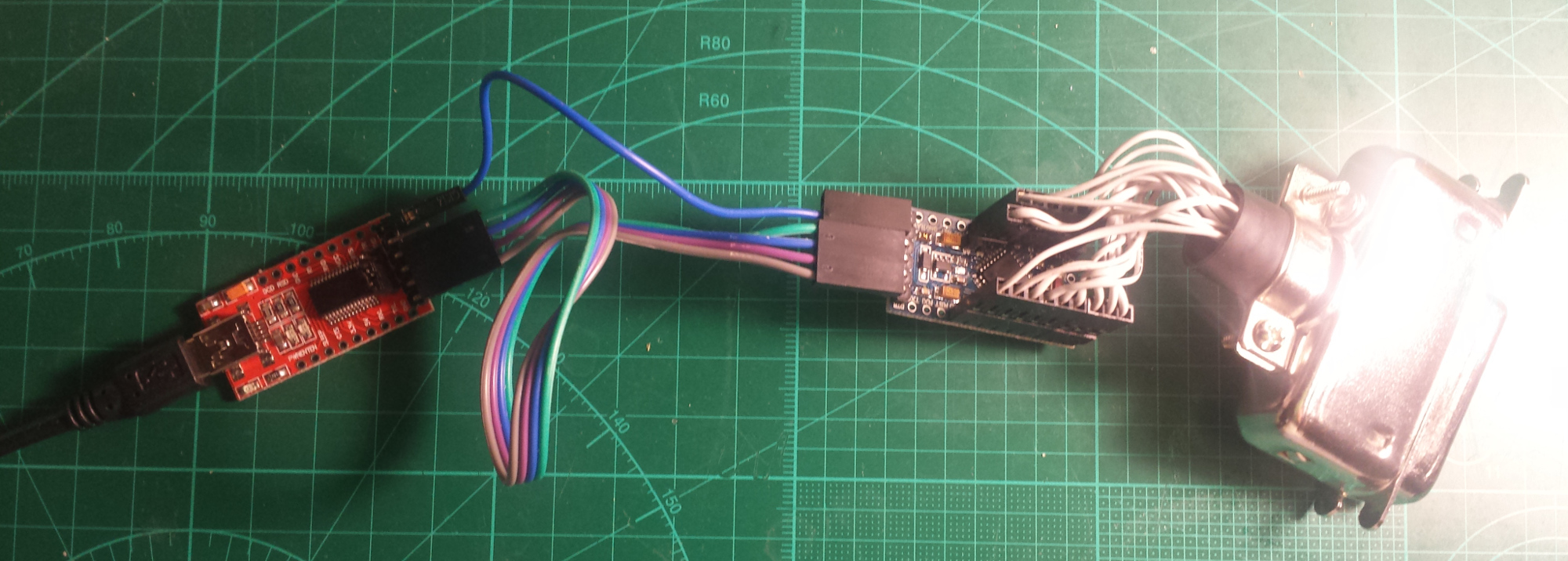
BASIC hp3478ext IMPLEMENTATION
If you just want a GPIB adapter, this basic variant is all you need.
This is also the simplest way to try it as an HP 3478A extension, but then there are some limitations:
1. Needs external (USB) power.
2. External connection to an HP 3478A takes some space.
3. Needs some kind of case to be used safely.
4. Doesn't have a buzzer for the continuity tester.
PARTS LIST
ATmega328P module, 5V, 16MHz
An Arduino Pro Mini-compatible board. The project doesn't use the Arduino environment, just the board.
https://www.ebay.com/sch/i.html?_nkw=arduino+pro+mini
USB-UART converter module
For example, an FTDI FT232RL-based or a Silicon Labs CP2102-based board would work. It should have a DTR pin and be 5V tolerant. You'll need an FT232RL, if you want to take advantage of the 2M baud rate.
https://www.ebay.com/sch/i.html?_nkw=usb+uart
GPIB cable or connector
It seems to be easier to find a cable than a connector.
https://www.ebay.com/sch/i.html?_nkw=gpib+connector
CONNECTIONS
Wire the GPIB connector to the ATmega328P as shown in the table, below. The first column contains the pin assignments for the GPIB connector. The last column contains the pin assignments for the 328P. It has Arduino pin names silkscreened on the module.
/*
 GPIB|       |                    |            | ATmega  |
 pin | name  | description        | direction  | pin     |
 ----+-------+--------------------+------------+---------+
 1   | DIO1  | Data bit 1 (LSB)   | Talker     | PD2  32 | 2
 2   | DIO2  | Data bit 2         | Talker     | PD3   1 | 3
 3   | DIO3  | Data bit 3         | Talker     | PD4   2 | 4
 4   | DIO4  | Data bit 4         | Talker     | PD5   9 | 5
 5   | EOI   | End Of Identity    | Talker     | PB3  15 | 11
 6   | DAV   | Data Valid         | Controller | PB4  16 | 12
 7   | NRFD  | Not Ready For Data | Listener   | PC0  23 | A0
 8   | NDAC  | No Data Accepted   | Listener   | PC1  24 | A1
 9   | IFC   | Interface Clear    | Controller | PC2  25 | A2
 10  | SRQ   | Service Request    | Slave      | PC3  26 | A3
 11  | ATN   | Attention          | Controller | PC4  27 | A4
 12  |       | Shield             |            |         |
 13  | DIO5  | Data bit 5         | Talker     | PD6  10 | 6
 14  | DIO6  | Data bit 6         | Talker     | PD7  11 | 7
 15  | DIO7  | Data Bit 7         | Talker     | PB0  12 | 8
 16  | DIO8  | Data bit 8 (MSB)   | Talker     | PB1  13 | 9
 17  | REN   | Remote Enabled     | Controller | PC5  28 | A5
 18  |       | GND DAV            |            |         |
 19  |       | GND NRFD           |            |         |
 20  |       | GND NDAC           |            |         |
 21  |       | GND IFC            |            |         |
 22  |       | GND SRQ            |            |         |
 23  |       | GND ATN            |            |         |
 24  |       | GND data           |            |         | GND

     | LED   |                    | OUT        | PB5     |
     |BUZZER | Buzzer PWM (OC1B)  | OUT        | PB2     |
*/
Connect the ATmega328P to the UART module as follows:
	TX	-	RXO
	RX	-	TXI
	GND	-	GND
	DTR	-	GRN
	5V	-	VCC
FLASHING THE FIRMWARE
A link to the hex
and EEPROM files
can be found on the project page
at
https://kirill-ka.github.io/hp3478ext/
The EEPROM .eep file contains the default settings and is only needed if the EEPROM gets corrupted for some reason. The firmware is flashed with the following avrdude command (assuming the standard bootloader is pre-programmed on the Atmega, which is usually the case):
avrdude -b 57600 -c arduino -p m328p -P /dev/ttyUSB0 -U flash:w:hp3478-ext.hex
Change /dev/ttyUSB0 to the appropriate port for your USB-UART converter module.
Note: You could probably flash the hex file using the Arduino IDE. I don't use it, so I don't know.
Important: I highly recommend setting the brownout detection fuses to 4.3V. The reason for this is that the ATmega will be powered by GPIB signal lines when the USB is disconnected. Then, it tends to hang and corrupt its EEPROM. Note that fuse programming can't be done via the bootloader and requires an ISP programmer. The command for setting the fuses is as follows:
avrdude -c dragon_isp -p m328p -Uefuse:w:0x04:m